Darla McFarren
Bicycle Generator
May 12, 2000
Purpose
The purpose of the bicycle generator is to use a model to describe a
concept of physics, namely energy conversion. The basic idea of my energy
conversion model in the bicycle generator shows how mechanical energy, such
as the energy expended on a bicycle, is converted into electrical energy.
This electrical energy can be used for a variety of electrical devices.
Once completed and finished this model may be used to demonstrate Faraday's
law of induced current in a moving magnetic field, or to demonstrate the
principles of energy with time.
Introduction
My hypothesis was that I could take a bicycle that uses mechanical
energy from the user. This mechanical energy is transferred from the bicycle's
pedals to the pulley of a car alternator. By using a 12-Volt battery, I would
supply current to the moving alternator to start the alternator current.
I would then disconnect the battery, becoming the only source of current in
the system. The output current from the alternator would then be used to run
an electrical device such as a light bulb.
Procedure
In making the Bicycle Generator, there were several steps involved.
First, I constructed a working alternator-battery circuit based on a circuit
by Eugene Brott of Concordia University. Using this circuit I was able to
take a salvaged bicycle and alternator and wire the alternator to a light bulb.
The bicycle generator was then mounted on plywood to stabilize the unit, and
I then took measurements of the unit.
Apparatus and Operation
I used the circuit of Eugene Brott for a model for my own circuitry.
Here is the circuit that was used in the making of the bicycle generator.

The alternator sections in the circuit are abbreviated to show the general
circuitry, rather than individual components of the circuit. The alternator
circuitry is from Chilton's Auto Repair Manual 1980-1987.
The alternator connects to the rest of the circuit by two flat
terminals numbered 1 and 2, as well as the battery terminal. The case of
the alternator is grounded with the grounds of the other items in the circuit.
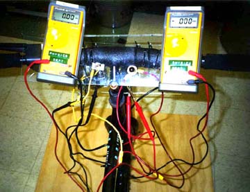
The top panel of the circuit houses the switches and the meters,
while the front panel houses a car headlight. The battery is connected to
the rest of the circuit by momentary switch S1, which is normally open.
Equipment
- Salvaged 10-speed bicycle that is set to one gear
- Rebuilt Delco-Remy 1986 Cavalier Alternator with a 5 grooved, V-ribbed pulley, internal voltage regulator and a rectifier bridge
- 12 Volt automobile battery
- 5 grooved V ribbed flat belt
- One 12.8 Volt, 50 Watt tungsten car headlight
- Ammeter
- Voltmeter
- Plexiglass, plywood and a bicycle trainer for mounting the bike and circuit
- One momentary switch, normally open to control current from car battery
- One toggle switch to control current into the headlight
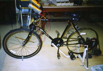
I converted a ten-speed bicycle into a one-speed bicycle by shortening the chain
to a specific length, and disconnecting the gear changer. Then I removed the
back wheel and tube, leaving only the rim and spokes of the back tire. This
rim provides a channel for a V-ribbed flat belt to be driven on the rim. The
belt then connects to the alternator pulley. As the pedals on the bicycle are
moved, the bicycle chain moves the back wheel, which causes rotation of the
alternator pulley through the flat belt.

The alternator, which is run by the pedaling of the user becomes the method
that converts the mechanical energy to electrical energy. An alternator does
not supply its own voltage to create additional current, so an outside voltage
must initially start the alternator. This voltage is created by connecting a
12 volt battery to a momentary switch that is normally open. This switch allows
the user to connect the battery in the circuit whenever he/she pleases.
The alternator current works best if the user of the bicycle generator is
pedaling at a high speed before pressing the normally open momentary switch.
Once the battery is disconnected from the system and the user is still pedaling
the bicycle, one can see with the meters that current is still found in the
system. At this point the user becomes the source of current in the system
through the moving parts of the alternator. Inside the alternator are coils
that move, called the rotary coils and coils that are stationary, called the
stator coils. The rotary coils move position based on the movement of the
alternator pulley. The movement of coils inside a magnetic field produces
alternating current in those moving coils. We can see that in the use of
Faraday's law.

This states that the change in flux over time creates an electromotive force.
The change in flux can be described in terms of both a change in area over a
constant magnetic field and the change of magnetic field with a constant area.
This creates current in the circuit that come from the stator coils to power
the rest of the circuit.
Through the use of a rectifier bridge the resulting alternating current
becomes converted into direct current that an electrical device can use.
Also inside the alternator is a voltage regulator, which adjusts the resistance
in the system to keep the output voltage at a constant value. The circuitry
of both the rectifier bridge and the regulator are complicated and we will
not focus on them.
When connecting the alternator to the bicycle with the belt system, it is
important to keep a constant tension of the belt so that the alternator is
running at a good efficiency. In this system, the farther away the
alternator, the more tension in the belt, and the more friction between
the belt and the pulley. As the friction increases here, we lose some
energy from heat, but gain more energy because the alternator spins faster.
Looking at the remaining structure of the bicycle generator, we see two
mounts that are in front of the user. One mount is facing the user,
holding the two switches and two meters for measuring current and voltage.
The other mount is in front of the bicycle and its placement represents
the placement of a car headlight system. The user should generate enough
current to be able to see the light bulb shine on the objects in front of
the user even if the headlight cannot be seen directly.
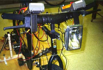
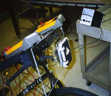
To aid in measuring the amount of illumination of the headlight I have
attached a photometer to the front of the system when taking data.
Data
Now that we have seen the basic construction of the bicycle generator
and talked about the alternator - battery system, we now shift our focus
to the data that was collected. This data is both quantitative and
qualitative. Looking at the quantitative data first, we see many relationships.
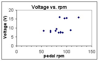
The first relationship we want to look at is the Voltage in the system
with the "speed" of the human pedaling the bicycle, denoted as pedal
revolutions per minute (rpm). The speed was found using a stop watch
and counting the number of revolutions during a set amount of time.
We see in this relationship that the voltage is essentially constant
while the speed changes. There are two lines of constant voltage,
one around 8 Volts and the other around 15 Volts. As we look at the
separation of these two lines, we must see the effects of tension on
the system. I noticed a change in the tension in the middle of taking
data points, and the more tension in the system, the more voltage I was receiving.
I did not think that the tension accounted for all of the voltage between
8 Volts and 15 Volts. One other possibility besides tension in the circuit
may be the voltage regulator in the alternator. At about 80 pedal rpm's the
break occurs. This corresponds with the alternator rpm of 1700, using a 21:1
ratio. It almost seems that the regulator is keeping two constant voltages.
This may be du to the circuit of the regulator that has a series of diodes.
The best explanation still is the tension in the system.
Next, we want to look at the current going to the headlight with the speed
of the pedaling. We again see the consistency of the current in the system
with changing revolutions per minute of the human pedaler. We notice a small
break here at the same speed, where current branches to a higher and lower
amount of current.
I don't expect the current from the alternator to be essentially constant.
From my understanding of the voltage regulator, there should be an increase
of current with an increase of speed. Perhaps there is something happening
in the regulator more than only voltage regulation. The induced emf and thus
induced current in the system is dependant upon the time that the changing
magnetic field travels past an area. As the speed of the alternator increases,
the amount of time that the magnetic field moves past the area decreases,
and then less emf would be induced. This is the only explanation to the
consistency in the current with the voltage.
This theory doesn't work, because hooking up an incandescent light bulb
to the circuit, we see that the illumination increases when we pedal faster.
This would imply that power is increasing and thus current should also be
increasing with greater speeds.

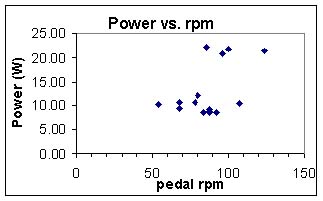
The third relationship that we will look at will be the power output of
the alternator with the speed of the alternator. We get these values by
multiplying the values of current and voltage together in the last
relationships. From our steady current and voltage values, we see that
we get steady power out of the alternator in values of about 22 Watts or
10 Watts.
The tension rule is the one that works best to explain the big gap between
the two regions of power. If the voltage was regulated and the current was
also regulated, then we would see a spread of values in between 10 and 22
Watts. If the regulator happened to "kick-in" at 80 pedal rpm's and allow
more voltage to be output, then anything above 80 rpm's would be in the 20
Watt region. However, even after checking the circuit for discrepancies, at
speeds of above 80 pedal rpm's I was still getting powers to be in the 10 Watt
region. So the alternator must have had a variance in tension in the system.
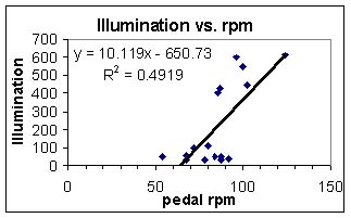
Focusing then on the illumination, we see a relationship that we expect.
We can physically see the incandescent light getting brighter when we pedal
faster. As the speed of the user increases in rpm, we see an increase in
the illumination, which is measured in lumens from a dark zero point.
If we separate out our two different points, we notice that there is a high
range of illumination and a low range of illumination. This is most likely
the result of the break in tension of the units where we saw a high power
range and a low power range.
If we look at the lower range, and focus on speeds of faster than 80 pedal
rpm's, we see more of a constant illumination rate. The constant current
and power with rpm tells us that the linear relationship of illumination
and rpm may be expected from our current circuit.
An argument for the linear line does come from the scale of the photometer.
The range of illumination in this area is so small compared to the range of
400 to 600. We were looking on a large scale when we took the data for the
smaller readings because we were expecting a range of 400-600 lumens. When
the tension had been decreased and we were getting voltages in the 8 volt
range, we were receiving illumination levels of 50-100 lumens. The constant
value of illumination in this region would be a result of approximations.
One last argument for the linear line could be that the photometer was
not very accurate in detecting lumens under 100. The photometer was not
calibrated and checked for accuracy before the experiment was taken.
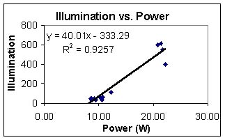
The illumination and speed relationship leads us to the illumination
and power relationship. We see that as the power of the system was
increased, we see an increase in illumination for our different groups.
The argument for this is the same as the argument for our other graphs.
The two groups may be a result of tension, or a result of the alternator itself.
Now we move to the qualitative data.
When the bicycle generator user first puts the 12 Volt battery into the
system, he/she notices that it is harder to pedal. This is because the user
is doing work in the system. If the battery is kept in the system
permanently, the user would do work to charge the battery.
Once the headlight is put into the system, the user notices another
increase in physical resistance of pedaling. Adding the headlight changes
the resistance in the circuit. The current in the system increases and
needs more physical energy to produce the higher amounts of current.
One last observation of qualitative data is the user's physical resistance
with the speed the user is going. At faster speeds, the user feels less
resistance from the alternator. At high speed the user's muscles are better
able to compensate for this decrease in physical resistance and can keep
the speed more constant than at lower speeds. At low speeds, the user
spurts energy in bursts based on the torque relationship of the bicycle pedals.
Conclusion
This model would be a good model to show how through mechanical energy,
one can create electrical energy. Users can observe the change in
brightness of the headlight, and feel the physical resistance of the
pedals with the change in circuitry.
In follow up, I can use this demonstration at a museum that is looking
for educational model to show the concepts of energy, but there would have
to be some modifications first. When using the bicycle generator as a
museum model, I would want to add a few more electrical apparatuses so
that the user can feel the physical resistance difference with different
loading resistors. The bicycle would have to be lowered or stabilized more
so children could use the bicycle because the bicycle frame is too high
for a child to reach. I would also want to encase the battery and the wire
joints so children would not get hurt.
If we are looking at a basic understanding of energy changing from
mechanical energy to electrical energy, this would be a good model
for the museum. A person could also discuss the energy created by the
user in terms of Joules and calories as another avenue of explaining how
energy is converted using the bicycle generator.
This model also lets us talk about physical concepts such as Faraday's
law and gives us a look at power and speed as well. This raises the level
of instruction to better suit high school and college students who are
talking about energy transformation, and electricity and magnetism.
The bicycle generator is a good model to show the concepts of energy and
does show how energy is transformed from a mechanical devise to an
electrical devise.